RemBus
RemBus is an industrial device that enables ModBus devices to communicate with eachother over a 2.4Ghz LoRa® link.

A RemBus device can be configured either in a Master or in a Slave mode.
- While in Master mode, the device acts as a ModBus controller, querying register values from other devices.
- While in Slave mode, the device responds to ModBus queries, forwarding the data received by a RemBus master.
1. Accessing the Configuration Interface#
To configure the device you must first place it in High-Power mode so that WiFi is turned on. This can be achieved in either of the following ways:
- If the device is configured not to sleep, the device will automatically start a WiFi Access Point once powered on.
- If the device is configured to sleep (eg. battery powered) you need to press the reset button 2 times. The device will acknowledge the high-power mode by a rapid double blink of the LED every 5 seconds.
Once the access point is enabled, you can connect to an Access Point named RemBus xx xxxxxxxx. You can then access the Web Interface under http://192.168.4.1.
2. Configuring Device Behaviour#
To configure the behaviour of the device, switch to the RemBus tab. There are 4 modules in this tab that controls the overall behaviour of the device.
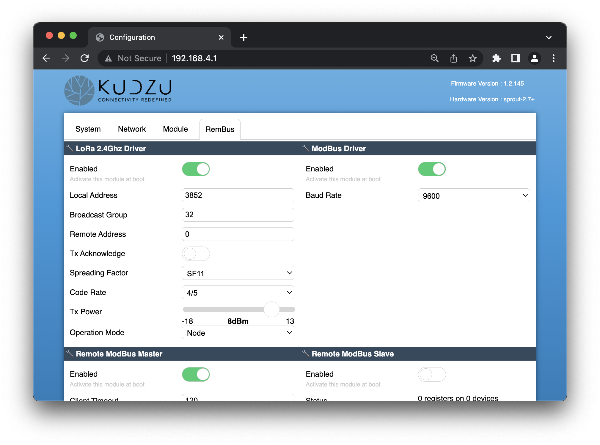
2.1. The ModBus Module#
This module configures the low-level details of the ModBus link. The only configurable option is the Baud Rate of the bus.
This needs to match the buad rate of the devices (or the master controller in slave mode).
2.2 The 2.4Ghz LoRa Uplink Module#
This module controls the wireless communication layer between the devices. In order for two devices to contact eachother they need to have similar configuration:
- The Spreading Factor, and Code Rate needs to be the same.
- They need to be on the same “Broadcast Group”, and the “Remote Address” must be set to 0.
- The “Remote Address” of the receiving device should be set in the interface of the sending device.
You should also make sure the value of the Operation Mode matches your configuration. RemBus Masters should use “Node” while RemBus slaves should use “Concentrator”.
2.3. The Remote Modbus Master Module#
When this module is enabled, you should disable the Remote Modbus Slave Module.
When this module is enabled, it will place a query over the ModBus line towards connected devices, asking them to return the values of their registers. It wil then send the data using the LoRa module.
Configure Device Queries#
You can configure the requests to be placed by providing up to 6 commands in the “Commands” fields. Every command is a sequence of hexadecimal bytes that should be sent as a ModBus query over the wire, without the CRC checksum.
A typical command looks like this:
010400010001
..            : The device address
  ..          : The function
    ........  : The function-specific payload
The commands supported are the following:
- (0x01) Read Coils
- (0x02) Read Discrete Inputs
- (0x03) Read Holding Registers
- (0x04) Read Input Registers
The device will collect the response to this command and send it over to the slave. If queried in the same way, the slave will respond the same data as this device has collected.
Timing Configuration#
There are three timers you can configure for your specific use-case:
The
Client Timeoutcontrols the time (in milliseconds) to wait until the ModBus device responds.The
Warm-Up Timeoutcontrols the time (in milliseconds) to wait before placing the first query in the bus. You can use this parameter for battery-powered setup, where the sensor requires some time after power-up before it can respond to queries.The
Poll Intervalis useful when the device is Mains-Powered and never sleeps. When set to a value greater than 0, it controls how long the device will wait before placing a second query to the sensors.
2.3. The Remote Modbus Slave Module#
When this module is enabled, you should disable the Remote Modbus Master Module.
When this module is enabled, it will listen for incoming messages from the LoRa module and keep all of their responses in memory.
When an incoming request from the ModBus is detected, it will look-up the response in the value table and will respond to the ModBus channel like a device, with the same values as the ones received.
This module has no configurable parameters.
3. Configuring Power Modes#
You can control the power settings of the device from the “System” tab.
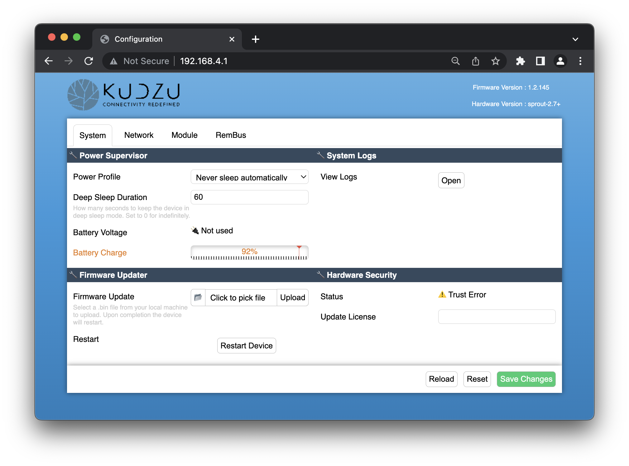
The Power Supervisor module is responsible for putting the device to sleep when there are no active opeartions.
Mains-Powered (or Bus-Powered) Mode#
If the device is powered by the mains, you can keep the device always on. To do this, select “Never sleep automatically” from the Power Profile.
Note that while in this mode you must specify a
Poll Intervalto the Remote Modbus Master Module, otherwise the device will query the sensors only once at boot.
Battery-Powered Mode#
If the device is powered by a battery, you need to put the device to sleep in order to conserve power. To do this, select the “Sleep when idle (Battery Mode)” option from the Power Profile.
The “Deep Sleep Duration” controls the interval (in seconds) at which the device will be woken-up from deep sleep and read-out the sensors.
4. Quick Guide Checklist#
If you want to configure a pair of devices to operate in Master/Slave mode, you can follow these checklists.
We are assuming that:
- One or more masters will be sending data to one slave
- The devices operate at 9600 Baud Rate
- The master devices are battery-operated
- The device has slave address
0x01and we will be reading 2 input registers starting from address0x0001 - The master will take a sample every 60 seconds
4.1. Configure a RemBus Master#
The RemBus master device is has the following two solder jumpers configured:
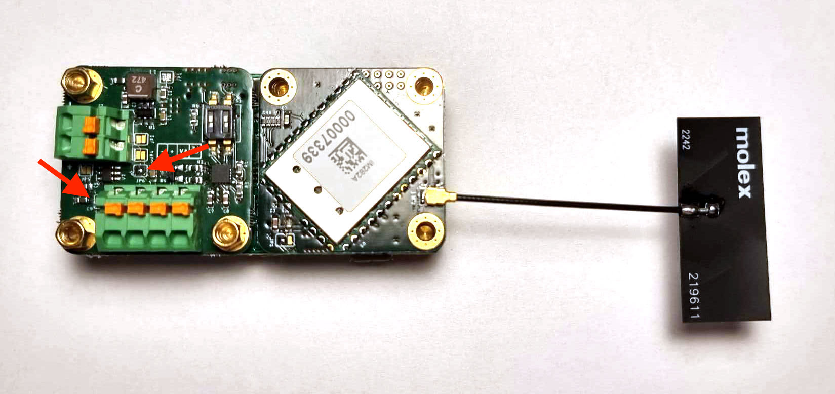
To configure such device:
Connect to the Web Interface
Switch to “RemBus” Tab
Turn on the “2.4Ghz LoRa Uplink” module
- Set the Broadcast Group to “32”
- Set the Remote Address to “0” (default)
- Disable “Tx Acknowledge” (default)
- Set “Spreading Factor” to SF11 (default)
- Set “Code Rate” to 4/5 (default)
- Set “Tx Power” to 8dBm (default)
- Set “Operation Mode” to “Node”
Turn on the “ModBus Driver” module
- Configure the Baud Rate to 9600
Turn on the “Remote ModBus Master” module
- Configure “Client Timeout” to 120 (default)
- Configure “Warm-Up Timeout” to 1000 (default)
- Configure “Poll Interval” to 0
- Set the first “Command” to be
010400010002
Turn off the “Remote ModBus Slave” module
Switch to “System” Tab
- Select “Sleep when idle (Battery mode)”
- Set “Deep Sleep Duration” to 60
Click “Save Changes”
4.1. Configure a RemBus Slave#
The RemBus master device is has the following three solder jumpers configured:
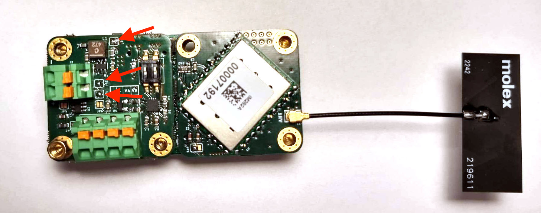
To configure such device:
Connect to the Web Interface
Switch to “RemBus” Tab
Turn on the “2.4Ghz LoRa Uplink” module
- Set the Broadcast Group to “32”
- Set the Remote Address to “0” (default)
- Disable “Tx Acknowledge” (default)
- Set “Spreading Factor” to SF11 (default)
- Set “Code Rate” to 4/5 (default)
- Set “Tx Power” to 8dBm (default)
- Set “Operation Mode” to “Concentrator”
Turn on the “ModBus Driver” module
- Configure the Baud Rate to 9600
Turn off the “Remote ModBus Master” module
Turn on the “Remote ModBus Slave” module
Switch to “System” Tab
- Select “Never sleep automatically”
Click “Save Changes”
5. Pinout & Wiring#
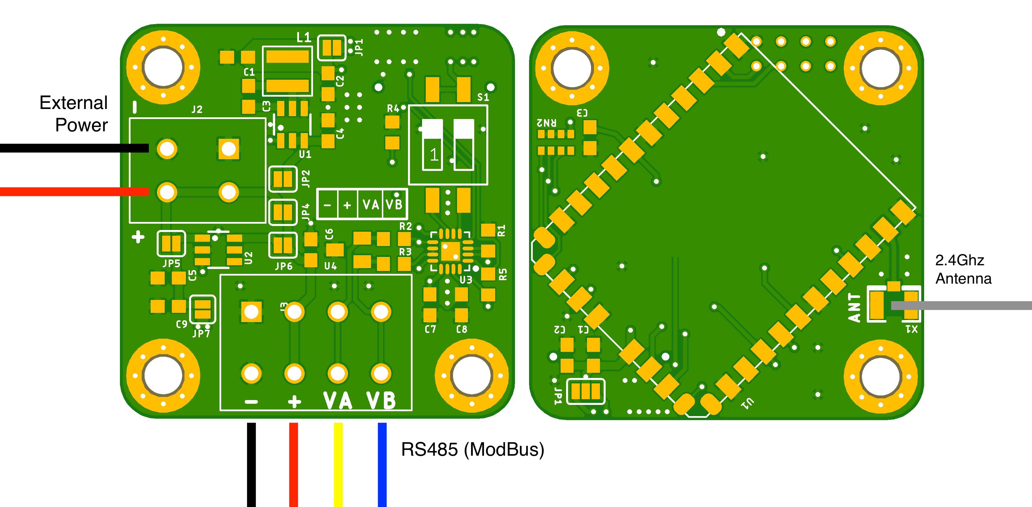
ModBus#
The device is connected to the RS485 ModBus cable via the 4-contact connector on top. The device is capable to either provide power to the bus, or to be powered by the bus.
The pinout of the bus can be seen on the schematic above and is also visible in a small table next to the DIP switch S1.
The 2 DIP switches (S1) control the bus termination resistors. If the device is the last one in the bus chain (or the only one), they should be turned on. This prevents signal reflections that can corrupt the data on the bus. The “ON” position is towards the edge of the board.
Power#
The device can be powered by a microUSB connector, a LiPo battery through a PH2.0 connector or through a dry cell battery pack via the same PH.2.0 connector. However, the ModBus extension can also be used for power delivery:
If JP1, JP2 and JP4 solder jumpers are configured, the device can be powered by the bus. This is a typical configuration mode for Slave. The bus voltage can be between 5V and 28V.
If JP6 and JP7 solder jumpers are configured, the device can control the voltage on the bus, being able to shut it off when the bus is not used. This is a typical configuration for Master. In this mode the device will deliver 5V to the bus.
If JP1, JP2, JP5 and JP6 solder jumpers are configured, the device can be operated by an external voltage up to 18V (not 28V). In this mode, the same voltage is also forwarded to the ModBus Bus. This is a typical rail-powered setup for higher-power Master configuration, where more than 5V needs to be delivered to the sensors.
LoRA Antenna#
The devie exposes a u.FL connector where a 2.4Ghz antenna can be attached. You can also use a pigtail connector (u.FL to SMA) if you want to provide the ability for an external attachment.
6. Troubleshooting#
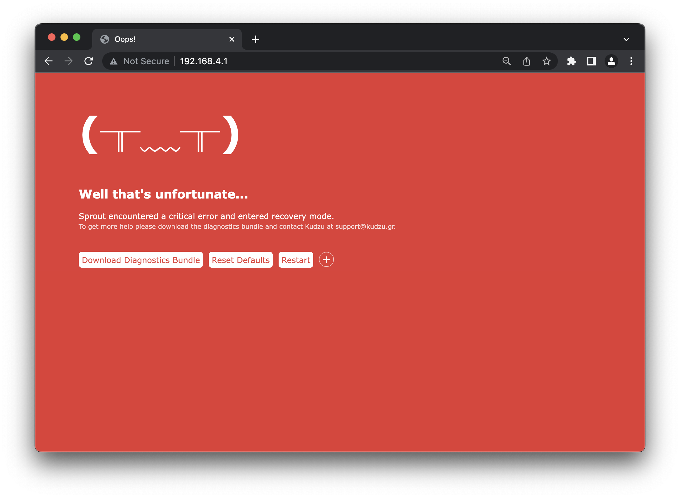
Note that at any point of time you can put the device in recovery mode by pressing the Reset button 5 times.
If the device encounters a critical issue it restarts in Recovery mode. During this mode, the LED blinks rapidly 5 every 1 second. At the same time it starts an Access Point named RECOVERY xxxxxxx.
If no device onnects to it after 30 seconds it turns off the WiFi and tries to self-recover by disabling the offending module. If it succeeds, the device might have limited functionality, but might be accessible for manual intervention.
While in recovery mode, the user can connect to the device and perform the following operations:
- Download a diagnostic bundle that can be used by Kudzu to remotely diagnose the origin of the failure.
- Perform factory reset of the device.
- Change the device firmware.